Add Your First Board
What you'll do: power on a board, let the manager discover it, and run through the setup wizard to name the board and assign your cockpit panels to it.
Before you begin
- The cockpit network is configured and the manager shows Listening on the Network page. See Set Up the Cockpit Network.
- The board is physically connected to your PoE switch and powered on.
Steps
1. Watch for the board to appear
Switch to the Network page in the manager. Within a few seconds of the board powering on, it appears in the board list with a NEW badge.
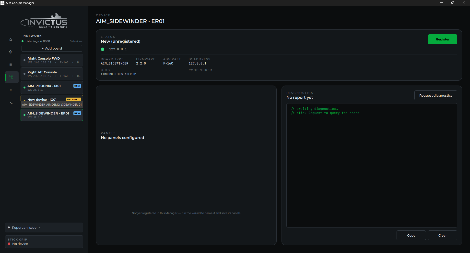
[!NOTE] If the board has been powered on before but never fully configured, it may show an UNCONFIGURED badge instead of NEW. Both badges open the same setup wizard.
2. Open the wizard
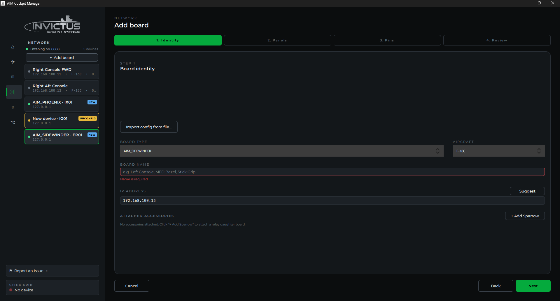
Click the board row (or the Set Up button that appears next to it). The board setup wizard opens.
3. Name the board
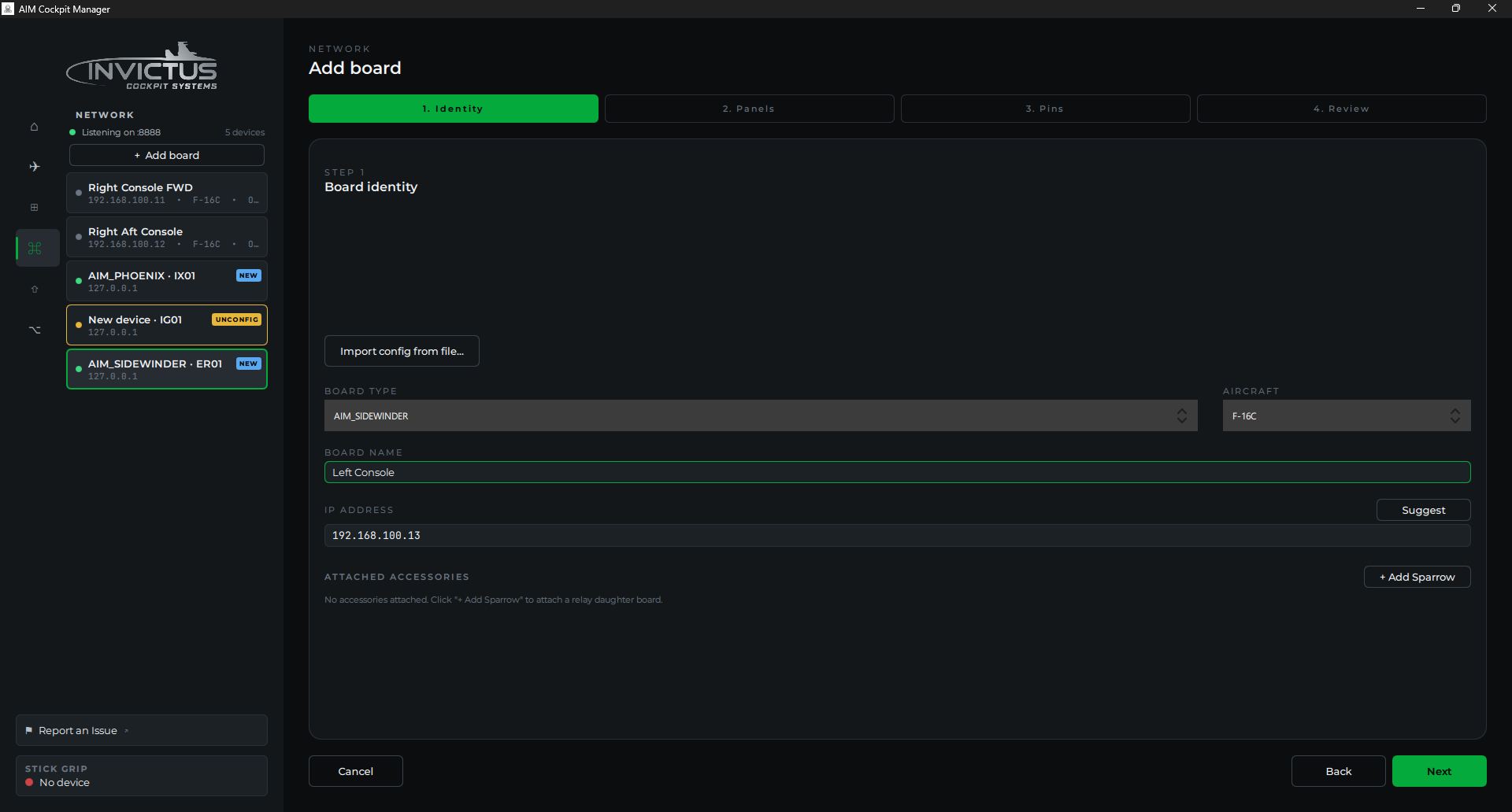
Give the board a name that tells you where it lives in the cockpit, for example, Left Console, Right Console Aft, or Instrument Panel. This name shows up in the board list and in every panel assigned to this board, so be specific if you have more than one board.
4. Pick the cockpit panels on this board
Select which F-16C panels will be physically wired to this board. The manager groups panels by cockpit location: Left Console, Right Console, Instrument Panel, and so on. Check each panel that has switches or knobs connected to this board's pins.
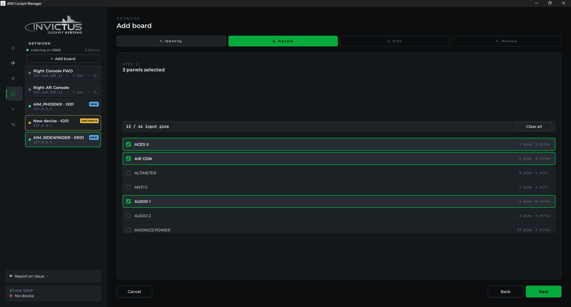
[!TIP] You can assign more panels later if you're not sure yet. It's easy to add or remove panels from a board after the wizard. You don't need to re-run it from scratch.
5. Assign an SPI channel (if applicable)
If any of the panels you selected have a physical display (UHF, CMDS) or a caution panel with indicator lights, the wizard asks which SPI channel on this board those devices are wired to. Pick SPI Channel 1 or SPI Channel 2 to match your wiring. If you're not wiring displays yet, skip this. You can set it later.
6. Assign pins to your controls
The wizard's Pins step lists every switch, knob, and lamp on the panels you picked. Assign each one to a pin on the board. Click Auto-assign to fill them in sequentially as a starting point, or set them by hand. Switches and indicators use one GPIO pin (three-position switches and encoders use two); pots use a potentiometer channel (P1-P8).
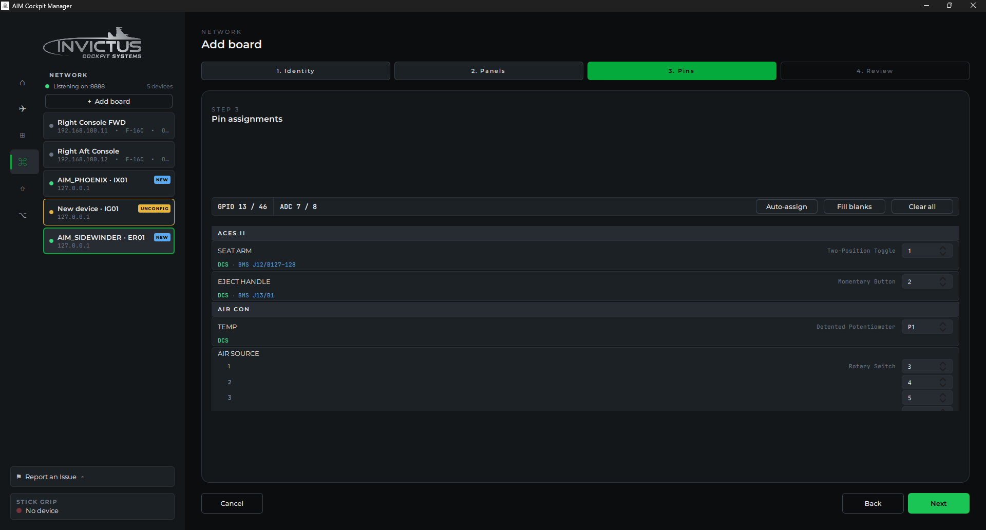
This is also where you plan your wiring. For the full workflow. Reviewing the auto-assignment, catching pin conflicts, and exporting a printable pin list to wire from; see Assign Controls to Pins.
7. Save
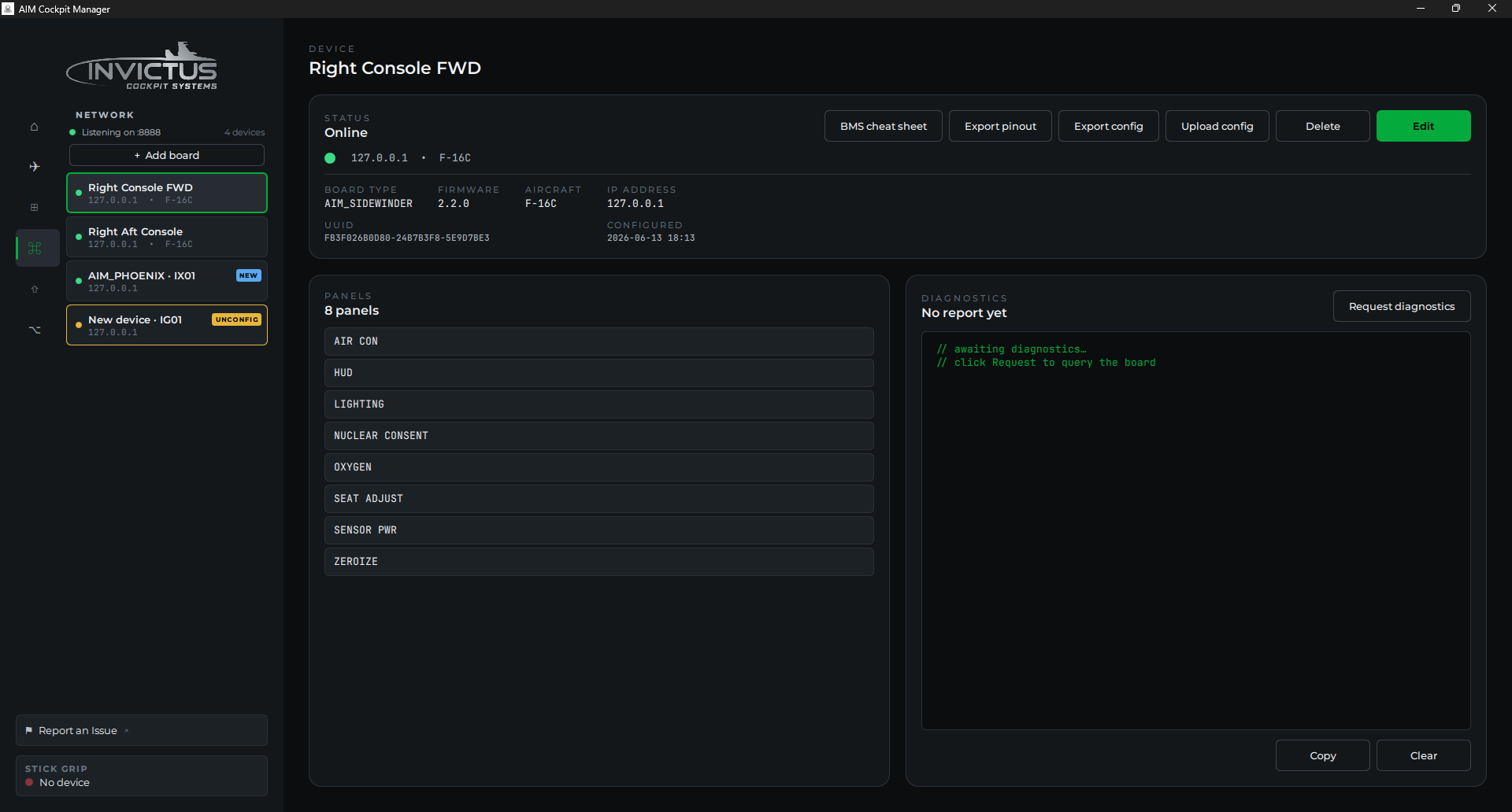
Click Save. The manager pushes the configuration to the board and assigns it a static IP on the cockpit network. The board reboots briefly and reappears in the list with a green dot and your chosen name.
Check it worked
The board row should show: - A green dot (connected and running) - Your chosen name - The board type (Sidewinder or Phoenix) - No badge (no NEW or UNCONFIGURED)
If something's wrong
| Problem | Fix |
|---|---|
| Board disappears after saving | Wait 10-15 seconds. The board reboots to apply its new config. If it doesn't reappear, check the PoE switch link light and try power-cycling the board. |
| Board reappears with UNCONFIGURED | The config didn't save. Check the network connection and try the wizard again. |
| Panels I need aren't in the list | Make sure you've selected the correct cockpit zone tab. If a panel is genuinely missing, contact support. |
Next: Assign Controls to Pins